Identity Relationship Diagrams
Searching back through the archives, I realized that I had first used the term “Identity Relationship Diagram” in a blog post on July 21, 2005. I stated then:
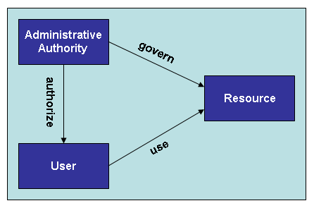
In the discipline of database design, Entity Relationship diagrams are used to diagram database schemas. In a database, neither entity nor relationship is complete without the other. It is the definition of relationship between data elements that adds value – hence the pervasive utility of the relational database.
A simple “Identity Relationship Diagram” (my term) helps to illustrate the concept. Identities are shown in boxes; relationships are shown as arrows.

More recently, following Ian Glazer’s proposal that graph databases replace directories and relational databases in Identity systems, I discussed using directed graph diagrams to illustrate identities and relationships:
We can visualize identities as nodes, each with relevant properties, and relationships between identities as edges. Â Interestingly, the edges, or relationships, may also have identities and properties of their own. Â
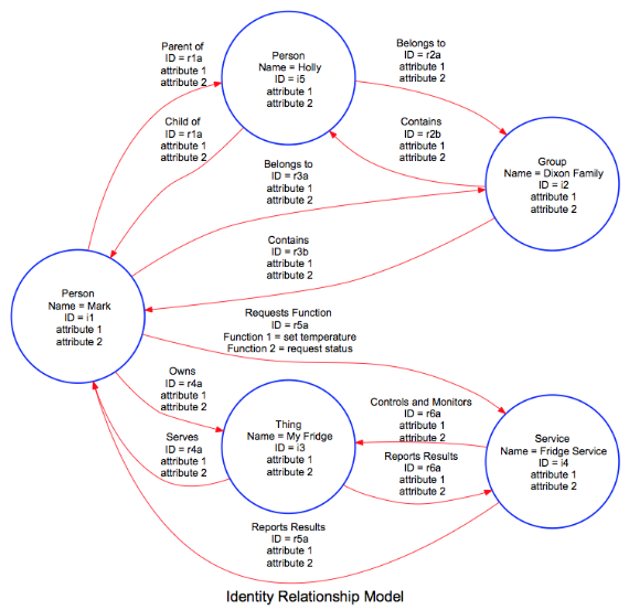
After further study and thought, I believe that “Identity Relationship Diagrams” can be very useful in illustrating concepts in the Identity and Access Management domain. The following diagram, prepared using Graphviz graph visualization software, is helpful to illustrate two general areas of discussion.

The top half of the diagram illustrates basic relationships between individuals how those individuals can belong to groups. Â This is the basic construct of the Facebook Identity Graph.
The bottom half of the diagram illustrates how people interact with things via services. Â These are the basic elements in the Internet of Things.
My thoughts about how to use this diagramming method are still developing. Â Stay tuned for more.
PS. Â For those interested in trying out the Graphvis software, the Dot graph description language code to create this diagram is:
## Entity Relationship Diagram – prepared by Mark Dixon
digraph test {
rankdir=LR;
graph [ fontname = “Arial”, fontsize = 20, size = “20,10” ];
node [shape=circle,fixedsize=true,width=2.5,color=blue,style=bold, fontname = “Arial”];
edge [color=red, fontname = “Arial”];i1 [ label=”Person\n Name = Mark\n ID = i1\n hair color = white\n residence = US”];
i2 [ label=”Group\n Name = Dixon Family\n ID = i2\n attribute 1\n attribute 2″];
i3 [ label=”Thing\n Name = My Fridge\n ID = i3\n attribute 1\n attribute 2″];
i4 [ label=”Service\n Name = Fridge Service\n ID = i4\n attribute 1\n attribute 2″];
i5 [ label=”Person\n Name = Holly\n ID = i5\n hair color = brown\n residence = UK”];i1->i5 [ label = “Parent of\n ID = r1a\n attribute 1\n attribute 2” ];
i5->i1 [ label = “Child of\n ID = r1a\n attribute 1\n attribute 2” ];i5->i2 [ label = “Belongs to\n ID = r2a\n attribute 1\n attribute 2” ];
i2->i5 [ label = “Contains\n ID = r2b\n attribute 1\n attribute 2” ];i1->i2 [ label = “Belongs to\n ID = r3a\n attribute 1\n attribute 2” ];
i2->i1 [ label = “Contains\n ID = r3b\n attribute 1\n attribute 2” ];i1->i3 [ label = “Owns\n ID = r4a\n attribute 1\n attribute 2” ];
i3->i1 [ label = “Serves\n ID = r4a\n attribute 1\n attribute 2” ];i4->i3 [ label = “Controls and Monitors\n ID = r6a\n attribute 1\n attribute 2” ];
i3->i4 [ label = “Reports Results\n ID = r6a\n attribute 1\n attribute 2” ];i1->i4 [ label = “Requests Function\n ID = r5a\n Function 1 = set temperature\n Function 2 = request status” ];
i4->i1 [ label = “Reports Results\n ID = r5a\n attribute 1\n attribute 2” ];Â
overlap=false
label=”Identity Relationship Model”}
